Buy the Book
Published By Lankelma
Lankelma is the foremost contractor for onshore in-situ soil testing in the UK. An acknowledged
specialist in CPT, Lankelma also offers a worldwide consultancy and training service.
A.P. van den Berg develops, designs and manufactures geotechnical and environmental soil
investigation equipment for onshore and offshore applications. Specialists in CPT systems and equipment.
Gardline
Gardline Geosciences offers worldwide marine geotechnics, in-house consutancy and services with marine
investigations ranging from nearshore to full ocean depth (down to 3000m).
About the Author
Hans Brouwer studied civil engineering at Delft University in The Netherlands. He has
worked as a part-time lecturer at Amsterdam Polytechnic and was senior partner in a structural
engineering consultancy. He has written a standard textbook in Dutch about the design of
building foundations. He now lives in England where he writes technical textbooks in
English, hopefully to reach a bigger readership.
Quick Links:
Chapter 1
Introduction
Introduction
History
The first penetrometer tests were made in the Netherlands in 1932. A
gas pipe of 19 mm inner diameter was used; inside this a 15 mm steel
rod could move freely up and down. A cone tip was attached to the steel
rod. Both the outer pipe and the inner rod with the 10 cm2 cone and a
60° apex angle were pushed down.
In 1935, Delft Soil Mechanics Laboratory in the Netherlands designed
the first manually operated 10 tonne cone penetration rig. The cone
was first pushed down 150 mm (maximum stroke) and then the outer
pipe was pushed down until it reached the cone tip. Then the casing and
the inner rods were pushed down together until the next level was
reached and the tip resistance could be measured again.
Later, there was an improvement by adding a conical part just above
the cone (Figure 1a on page 2). The purpose of this new geometry
was to prevent soil from entering the gap between the casing and the
inner rods.
In 1953, there was a significant improvement to the Dutch cone test by
adding a friction sleeve behind the cone (Figure 1b). Using this new
device, the local friction could be measured in addition to the cone
resistance. Measurements were made every 0.2 m. For the first time it
was proposed that the friction ratio (sleeve friction / cone resistance)
could be used to classify soil layers in terms of soil type.
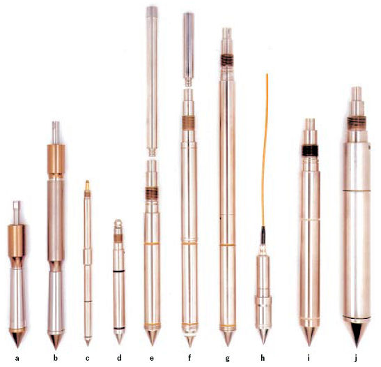 |
Figure 1 Penetrometers, developed over time (Source: A P van den Berg) |
a
b
c
d
e
f
g
h
i
j | Mechanical cone with conical mantle (1948)
Mechanical cone with friction sleeve (1953)
2 cm2 electrical friction cone (1998)
5 cm2 electrical friction cone (1997)
10 cm2 electrical piezo cone for wireless testing (1997)
10 cm2 electrical piezo cone (1994)
10 cm2 electrical seismic cone (1998)
10 cm2 disposable piezo cone (1988)
15 cm2 electrical friction cone (1989)
25 cm2 electrical friction cone (1986) |
In the 1960s, an electric cone was developed. The shape and
dimensions of this cone formed the basis for the International Test
Procedure (ISSMGE, 2001[1]). The main improvements relative to
mechanical cone penetrometers were: the elimination of reading errors due to friction between inner rods
and the outer tubes
a continuous testing with a continuous rate of penetration but without
the need for alternative movements of different parts of the
penetrometer, therefore influencing the cone resistance
a continuous reading of the cone resistance and easy recording of
the results.
Figure 1 above shows the different stages of development of the
cone penetrometer.
Since 1974, a large number of piezo cones have been developed, with
different shapes and filter positions. Some had filters on the very tip or
midway on the cone tip and some on the cylindrical part just behind the
cone tip. In practice most tests were done with the filter on the cone
face. Gradually the practice has changed so that the recommended
position is close behind the cone. With the measurement of porewater
pressure it became apparent that it was necessary to correct the cone
resistance for porewater pressure effects, especially in clay.
|
<< Previous PageNext Page >>